|
|
|
AISG to
D-SUB 9PIN Cable: |
The AISG
control cables are used to feed data and power from the
controller to the RET (remote electrical tilt) system
components.
These cables are available in various lengths and are
terminated with male and female connectors which allow them
to be linked together to meet a required length.
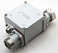
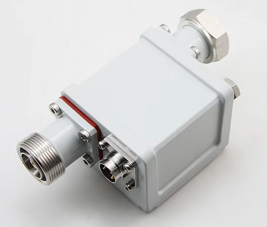
GELVO recommends grounding the RET control cable at the top
of the tower using a junction box. A lightning protection
unit should be used at the bottom of the tower to ground the
RET control cable. |
|
|
Structure Dimension: |
|
No.
|
Model
|
Cable Length |
Remark
|
|
A
|
AISG/F-DB9/M-0.5M/ |
0.5m |
AISG DIN
Female to DB9 Male |
|
B
|
AISG/F-DB9/M-1.0M/ |
1.0m |
AISG DIN
Female to DB9 Male |
|
C |
AISG/F-DB9/M-3.0M/ |
3.0m |
AISG DIN Female
to DB9 Male |
|
D |
AISG/F-DB9/M-5.0M/ |
5.0m |
AISG DIN Female
to DB9 Male |
|
E |
AISG/F-DB9/M-6.0M/ |
6.0m |
AISG DIN Female
to DB9 Male |
|
F |
AISG/F-DB9/M-10.0M/ |
10.0m |
AISG DIN Female
to DB9 Male |
|
G |
AISG/F-DB9/-15.0M/ |
15.0m |
AISG DIN Female
to DB9 Male |
|
H |
AISG/F-DB9/M-30.0M/ |
30.0m |
AISG DIN Female
to DB9 Male |
|
I
|
AISG/F-DB9/M-50.0M/ |
50.0m |
AISG DIN Female
to DB9 Male |
|
J
|
AISG/F-DB9/M-60.0M/ |
60.0m |
AISG DIN Female
to DB9 Male |
|
K
|
AISG/F-DB9/M-70.0M/ |
70.0m |
AISG DIN Female
to DB9 Male |
|
L
|
AISG/F-DB9/M-80.0M/ |
80.0m |
AISG DIN Female
to DB9 Male |
|
M |
AISG/F-DB9/M-90.0M/ |
90.0m |
AISG DIN Female
to DB9 Male |
|
N
|
AISG/F-DB9/M-100.0M/ |
100.0m |
AISG DIN Female
to DB9 Male |
|
|
Electrical Specifications:
Protocol AISG 1.1 | AISG 2.0
Voltage, maximum 300 V
Mechanical Specifications:
AISG Connector A 8-pin DIN Female
AISG Connector A Body Style Straight
AISG Connector A Standard IEC 60130-9
Connector D-SUB 9-pin Male
Data Conductor Type 0.20 mm² (24 AWG) twisted pair
Power Conductor Type 0.82 mm² (18 AWG) stranded
Color Black
Environmental Specifications:
Climatic Sequence Test Method IEC 60068-2-14
Corrosion Test Method IEC 60068-2-11, Test Condition
Ka
Operating Temperature -40 ¡ãC to +70 ¡ãC (-40 ¡ãF to
+158 ¡ãF)
Relative Humidity Up to 100%
UV Resistance Test Method IEC 60068-2-5, Test
Condition B
Ingress Protection Test Method IEC 60529:2001, IP67
Dimensions:
Length 1.0 m~100m
Diameter Over Jacket 8.0 mm
|
|
|
|
|
|
|
|
|
|
AISG to D-SUB 9PIN
CABLE |
 |
|
AISG to
D-SUB 15PIN Cable: |
The AISG
control cables are used to feed data and power from the
controller to the RET (remote electrical tilt) system
components.
These cables are available in various lengths and are
terminated with male and female connectors which allow them
to be linked together to meet a required length.
GELVO recommends grounding the RET control cable at the top
of the tower using a junction box. A lightning protection
unit should be used at the bottom of the tower to ground the
RET control cable. |
|
|
Structure Dimension: |
|
No.
|
Model
|
Cable Length |
Remark
|
|
A
|
AISG/F-DB15/M-0.5M/ |
0.5m |
AISG DIN
Female to DB9 Male |
|
B
|
AISG/F-DB15/M-1.0M/ |
1.0m |
AISG DIN
Female to DB9 Male |
|
C |
AISG/F-DB15/M-3.0M/ |
3.0m |
AISG DIN Female
to DB9 Male |
|
D |
AISG/F-DB15/M-5.0M/ |
5.0m |
AISG DIN Female
to DB9 Male |
|
E |
AISG/F-DB15/M-6.0M/ |
6.0m |
AISG DIN Female
to DB9 Male |
|
F |
AISG/F-DB15/M-10.0M/ |
10.0m |
AISG DIN Female
to DB9 Male |
|
G |
AISG/F-DB15/-15.0M/ |
15.0m |
AISG DIN Female
to DB9 Male |
|
H |
AISG/F-DB15/M-30.0M/ |
30.0m |
AISG DIN Female
to DB9 Male |
|
I
|
AISG/F-DB15/M-50.0M/ |
50.0m |
AISG DIN Female
to DB9 Male |
|
J
|
AISG/F-DB15/M-60.0M/ |
60.0m |
AISG DIN Female
to DB9 Male |
|
K
|
AISG/F-DB15/M-70.0M/ |
70.0m |
AISG DIN Female
to DB9 Male |
|
L
|
AISG/F-DB15/M-80.0M/ |
80.0m |
AISG DIN Female
to DB9 Male |
|
M |
AISG/F-DB15/M-90.0M/ |
90.0m |
AISG DIN Female
to DB9 Male |
|
N
|
AISG/F-DB15/M-100.0M/ |
100.0m |
AISG DIN Female
to DB9 Male |
|
|
Electrical Specifications:
Protocol AISG 1.1 | AISG 2.0
Voltage, maximum 300 V
Mechanical Specifications:
AISG Connector A 8-pin DIN Female
AISG Connector A Body Style Straight
AISG Connector A Standard IEC 60130-9
Connector D-SUB 15-pin Male
Data Conductor Type 0.20 mm² (24 AWG) twisted pair
Power Conductor Type 0.82 mm² (18 AWG) stranded
Color Black
Environmental Specifications:
Climatic Sequence Test Method IEC 60068-2-14
Corrosion Test Method IEC 60068-2-11, Test Condition
Ka
Operating Temperature -40 ¡ãC to +70 ¡ãC (-40 ¡ãF to
+158 ¡ãF)
Relative Humidity Up to 100%
UV Resistance Test Method IEC 60068-2-5, Test
Condition B
Ingress Protection Test Method IEC 60529:2001, IP67
Dimensions:
Length 1.0 m~100m
Diameter Over Jacket 8.0 mm
|
|
|
|
|
|
|
|
|
|
AISG to D-SUB 15PIN
CABLE |
|
|
|
¡¡ |
|
Over Mold AISG to
D-SUB 9PIN Cable: |
The AISG
control cables are used to feed data and power from the
controller to the RET (remote electrical tilt) system
components.
These cables are available in various lengths and are
terminated with male and female connectors which allow them
to be linked together to meet a required length.
GELVO recommends grounding the RET control cable at the top
of the tower using a junction box. A lightning protection
unit should be used at the bottom of the tower to ground the
RET control cable. |
|
|
Structure Dimension: |
|
No.
|
Model
|
Cable Length |
Remark
|
|
A
|
AISG/F-DB9/M-0.5M/ |
0.5m |
AISG DIN
Female to DB9 Male |
|
B
|
AISG/F-DB9/M-1.0M/ |
1.0m |
AISG DIN
Female to DB9 Male |
|
C |
AISG/F-DB9/M-3.0M/ |
3.0m |
AISG DIN Female
to DB9 Male |
|
D |
AISG/F-DB9/M-5.0M/ |
5.0m |
AISG DIN Female
to DB9 Male |
|
E |
AISG/F-DB9/M-6.0M/ |
6.0m |
AISG DIN Female
to DB9 Male |
|
F |
AISG/F-DB9/M-10.0M/ |
10.0m |
AISG DIN Female
to DB9 Male |
|
G |
AISG/F-DB9/M-15.0M/ |
15.0m |
AISG DIN Female
to DB9 Male |
|
H |
AISG/F-DB9/M-30.0M/ |
30.0m |
AISG DIN Female
to DB9 Male |
|
I
|
AISG/F-DB9/M-50.0M/ |
50.0m |
AISG DIN Female
to DB9 Male |
|
J
|
AISG/F-DB9/M-60.0M/ |
60.0m |
AISG DIN Female
to DB9 Male |
|
K
|
AISG/F-DB9/M-70.0M/ |
70.0m |
AISG DIN Female
to DB9 Male |
|
L
|
AISG/F-DB9/M-80.0M/ |
80.0m |
AISG DIN Female
to DB9 Male |
|
M |
AISG/F-DB9/M-90.0M/ |
90.0m |
AISG DIN Female
to DB9 Male |
|
N
|
AISG/F-DB9/M-100.0M/ |
100.0m |
AISG DIN Female
to DB9 Male |
|
|
Electrical Specifications:
Protocol AISG 1.1 | AISG 2.0
Voltage, maximum 300 V
Mechanical Specifications:
AISG Connector A 8-pin DIN Female
AISG Connector A Body Style Straight
AISG Connector A Standard IEC 60130-9
Connector D-SUB 9-pin Male
Data Conductor Type 0.20 mm² (24 AWG) twisted pair
Power Conductor Type 0.82 mm² (18 AWG) stranded
Color Black
Environmental Specifications:
Climatic Sequence Test Method IEC 60068-2-14
Corrosion Test Method IEC 60068-2-11, Test Condition
Ka
Operating Temperature -40 ¡ãC to +70 ¡ãC (-40 ¡ãF to
+158 ¡ãF)
Relative Humidity Up to 100%
UV Resistance Test Method IEC 60068-2-5, Test
Condition B
Ingress Protection Test Method IEC 60529:2001, IP67
Dimensions:
Length 1.0 m~100m
Diameter Over Jacket 8.0 mm
|
|
|
|
|
|
|
|